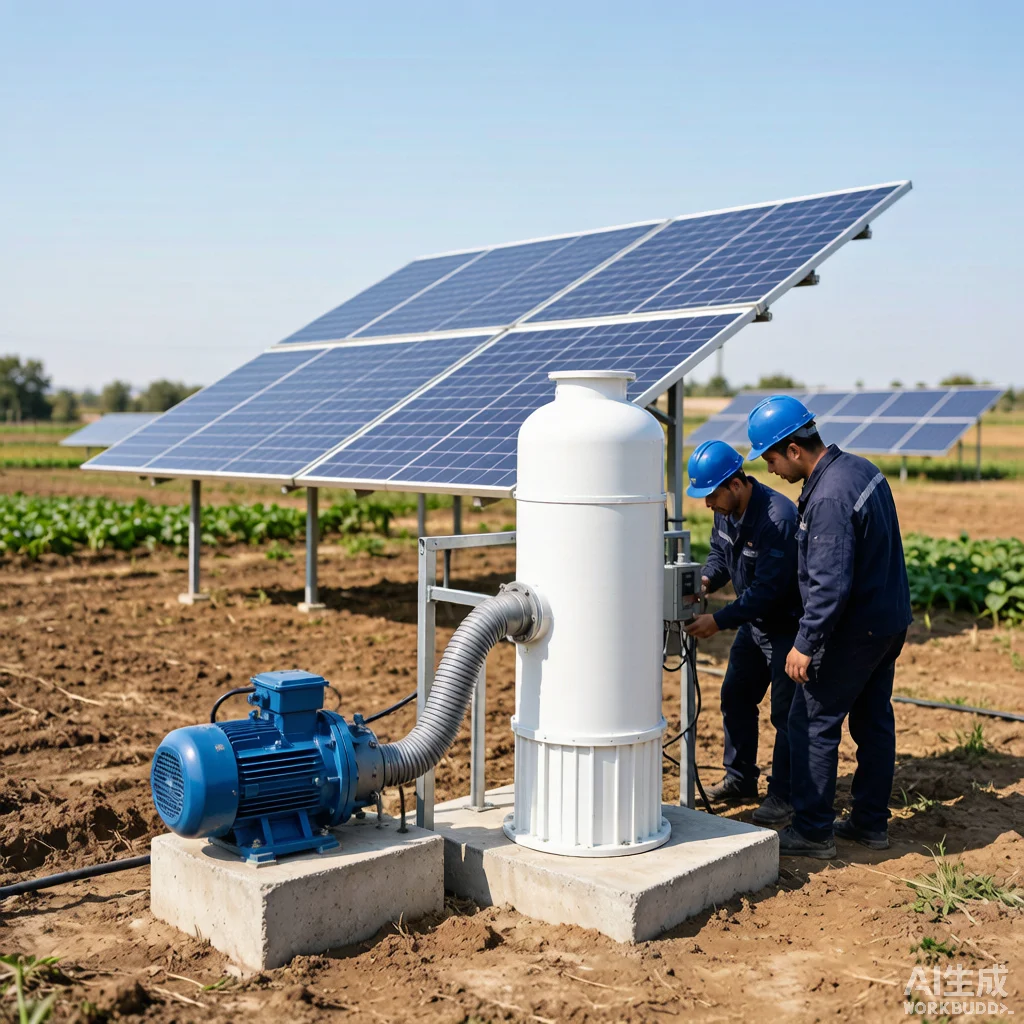
Solar Pump System Protection: Surge Arresters and Electrical Safety Design
Introduction
Solar water pumping systems operate in exposed outdoor environments where lightning strikes and electrical surges represent a critical threat to equipment longevity and operational reliability. A single lightning event within 1 km of an installation can induce transient overvoltages exceeding 6 kV on DC cabling, sufficient to destroy photovoltaic inverters, motor controllers, and submersible pump electronics in microseconds. KINBO, as a manufacturer of solar water pumps deployed across agricultural, community water supply, and industrial applications globally, integrates comprehensive surge protection and electrical safety design into system engineering from the ground up. Understanding the hierarchy of surge protective devices (SPDs), proper grounding topology, and coordination with overcurrent protection is essential for installers, system integrators, and end-users who depend on uninterrupted water supply. This article provides a technically detailed guide to lightning and surge protection for solar pumping systems, referencing IEC 62305 and IEC 60364 standards, with practical design parameters that can be applied directly in the field.
Table of Contents
Lightning and Surge Protection Fundamentals — Type 1/2/3 SPDs
Surge protective devices for solar pumping systems are classified into three types per IEC 61643-11, each serving a distinct position in the protection cascade. Type 1 SPDs (Class I, 10/350 μs waveform) are installed at the main electrical entry point — typically the AC service entrance or the DC combiner box where PV array conductors converge. These devices are tested to withstand 10/350 μs impulse currents with a nominal discharge current (Iimp) of 12.5 kA per pole minimum, and are designed to handle direct lightning current partial injection. For a typical 5–15 kWp solar pump installation, a Type 1 SPD with Iimp ≥ 12.5 kA and voltage protection level Up ≤ 2.5 kV is specified on the DC side at the array combiner box.
Type 2 SPDs (Class II, 8/20 μs waveform) provide the second stage of protection downstream, rated for a nominal discharge current In of 20 kA and maximum discharge current Imax of 40 kA. These are installed at sub-distribution boards, often at the point where DC cables enter the pump controller enclosure. The 8/20 μs waveform represents induced surges from nearby lightning strikes (within 500 m) or switching transients from the inverter. Critically, the let-through voltage from a Type 1 device alone — typically 1,500–2,500 V — can still exceed the withstand voltage of modern MPPT controllers (often rated 1,500 V DC maximum). A Type 2 SPD with Up ≤ 1,500 V is therefore essential at the controller input. Type 3 SPDs (Class III, combined waveform 1.2/50 μs — 8/20 μs) provide final equipment-level protection at the pump motor terminals themselves, with Up ≤ 1,000 V and In of 3–5 kA. Proper cascading of Type 1 → Type 2 → Type 3 devices with ≥10 m cable separation (or coordinated inductors) between stages ensures each SPD sees only the energy it is rated for, a principle known as energy coordination.
A complete solar pumping system requires SPDs on both DC and AC sides. On the DC side: one Type 1 SPD at the PV array combiner box, one Type 2 SPD at the pump controller DC input, and optionally a Type 3 SPD near the motor if cable length from controller to borehole exceeds 30 m. On the AC side (where grid backup or generator input exists): one Type 1+2 combined SPD at the main distribution board. For pure off-grid systems without AC input, DC-side protection alone is sufficient, but the grounding design becomes doubly critical.
Grounding System Design for Solar Pump Installations
The effectiveness of any surge protection scheme is directly limited by the quality of the grounding system. Lightning surge energy must find a low-impedance path to earth; a poorly designed ground with resistance exceeding 10 Ω will render even correctly specified SPDs ineffective. The foundation of solar pump grounding design is a single-point equipotential bonding network. All metallic structures — PV module frames, mounting rails, pump casing, controller enclosure, and surge arrester ground terminals — must be bonded to a common earth electrode system via copper conductors of minimum 16 mm² cross-section (per IEC 60364-5-54 for lightning protection applications).
Earth electrode design depends on soil resistivity, which must be measured on-site using the Wenner four-probe method before installation. For typical agricultural soils with resistivity ρ = 100–500 Ω·m, a vertical rod electrode of 1.5–2.4 m length provides a ground resistance R ≈ ρ/(2πL) × ln(4L/d). A single 2 m rod of 16 mm diameter in 200 Ω·m soil yields approximately R = 200/(2π×2) × ln(8/0.016) = 15.9 × 6.21 ≈ 99 Ω — unacceptable. Therefore, multiple rods in parallel are required: three rods spaced at a distance ≥ rod length reduce total resistance to approximately Rtotal = Rsingle / (n × 0.7) for n electrodes, bringing the example above to approximately 47 Ω. Adding a ring earth electrode (buried copper tape of 25×3 mm around the equipment pad at 0.5–1.0 m depth) further reduces impedance at high frequencies characteristic of lightning. For areas with ρ > 500 Ω·m, chemical ground enhancement materials or deep-driven electrodes reaching moist strata may be necessary.
A common and dangerous error in solar pump installations is connecting the DC negative conductor directly to earth without SPD coordination — this creates a direct path for surge current through the pump electronics. The grounding design must distinguish between functional earthing (which may or may not be required depending on inverter topology) and protective earthing (which is always required). For transformerless inverters, both DC+ and DC– must float relative to earth, with surge current routed exclusively through SPDs to the equipotential busbar. The borehole itself presents a unique opportunity: the steel casing, if present and accessible, can serve as a natural earth electrode with excellent contact to deep soil layers, often achieving 5–20 Ω resistance and can be bonded into the main earthing system.
Protection Coordination and Selective Disconnection
Surge protection does not operate in isolation — it must be coordinated with overcurrent protection devices (circuit breakers, fuses) to create a fully selective protection cascade. The principle of selectivity means that in the event of a fault, only the protective device closest to the fault operates, leaving upstream circuits energized and the rest of the system functional. For solar pumping installations, this coordination involves three layers: (1) PV array string overcurrent protection, (2) surge protective device coordination with backup overcurrent, and (3) motor overload and short-circuit protection at the pump controller.
PV string overcurrent protection uses DC-rated fuses (gPV type per IEC 60269-6) sized at 1.25 × Isc (short-circuit current) per string. For a 400 W module with Isc = 10.2 A, the fuse rating is 15 A DC. When multiple strings are paralleled (N > 2), each string requires individual fuse protection because backfeed current from the parallel combination can exceed the module’s reverse current rating under fault conditions. The SPD itself must be backed by an overcurrent device — typically a circuit breaker or fuse rated at the SPD manufacturer’s specified maximum backup overcurrent (usually 125–160 A gG for Type 1 SPDs). SPDs are designed to fail short at end of life; without backup overcurrent protection, a failed SPD becomes a permanent short circuit that can create a fire hazard and collapse the DC bus voltage.
Time-current coordination curves determine whether selectivity is achieved. The general rule: the downstream device must have a total clearing I²t value less than the upstream device’s pre-arcing I²t value at all fault current levels. In practical terms: a 15 A gPV fuse on a PV string must clear before the 125 A fuse backing the SPD begins to melt. For motor protection, modern solar pump controllers incorporate electronic overload protection with I²t modeling that matches the motor’s thermal time constant — typically 3–5 minutes for submersible motors rated 1.5–7.5 kW. The controller must be programmed to trip at 115–125% of rated motor current (per NEC 430.32 / IEC 60364-5-53) with a trip class of 10, 20, or 30 depending on motor starting duty. KINBO pump controllers ship with factory-configured protection parameters, but installers should verify these against actual site conditions, particularly for deep-set pumps where motor starting current can persist for extended periods due to high static head.
Electrical Safety Standards and Compliance — IEC 62305, IEC 60364
IEC 62305 “Protection Against Lightning” is the principal international standard governing lightning risk assessment and protection system design. It consists of four parts: Part 1 (General Principles), Part 2 (Risk Management), Part 3 (Physical Damage to Structures and Life Hazard), and Part 4 (Electrical and Electronic Systems within Structures). For a solar pumping installation, the risk assessment per IEC 62305-2 determines whether lightning protection is mandatory by calculating the tolerable risk RT versus the actual risk R. The calculation considers factors including lightning ground flash density Ng (flashes/km²/year, obtained from local meteorological data), the collection area of the installation, and the consequences of failure. For a solar pump system supplying critical drinking water to a community, the loss value L may be sufficiently high that protection is required even in regions with moderate lightning activity.
IEC 60364 “Low-Voltage Electrical Installations” provides the installation rules. Part 7-712 specifically addresses photovoltaic power supply systems, requiring that DC cables be double-insulated (Class II equivalent), that DC isolators be rated for 1.25 × Voc-max at minimum expected temperature, and that all DC circuit components be rated for continuous DC operation — AC-only breakers must never be used on DC circuits as they lack the arc-quenching capability required. Part 5-53 defines the requirements for isolation, switching, and control: every solar pump controller must have a lockable DC isolator within arm’s reach (per IEC 60364-5-537) rated for full PV array open-circuit voltage at the site’s minimum recorded ambient temperature, with a correction factor of approximately 1.2 for temperate climates (Voc at -10°C ≈ 1.12 × Voc at STC for typical crystalline silicon modules).
Additional relevant standards include IEC 61643-11 for SPD specifications and testing, IEC 60269-6 for DC fuse requirements, and IEC 62109-3 for safety of power converters for PV systems. Compliance is not merely a paperwork requirement — each standard codifies decades of failure analysis. Non-compliance with DC isolation requirements is responsible for a significant proportion of solar installation fire incidents. For KINBO systems, all electrical enclosure designs are pre-validated against these standards, but field verification of polarity, insulation resistance (≥1 MΩ at 500 V DC test voltage per IEC 60364-6), and SPD end-of-life indicators should be completed during commissioning and documented in the handover package.
For expert support with surge protection design and electrical safety compliance for your solar pumping system, contact KINBO.
Frequently Asked Questions
How many surge protection devices does a solar pump system need?
A properly protected solar pump system typically requires a minimum of three surge protection devices: one Type 1 SPD at the PV array combiner box on the DC side, one Type 2 SPD at the pump controller DC input, and one Type 1+2 combined SPD at the AC supply if grid or generator backup is present. For systems with borehole cable runs exceeding 30 m between the controller and submersible motor, a Type 3 SPD at the motor junction is also recommended. Large installations with multiple array sub-fields may require Type 2 SPDs at each sub-combiner box. The total number can range from 2–6 SPDs depending on system architecture.
What is the difference between Type 1 and Type 2 SPDs?
Type 1 SPDs (Class I) are tested with a 10/350 μs impulse waveform simulating direct lightning current injection, with typical ratings of Iimp = 12.5–25 kA per pole. They are installed at the service entrance and handle the highest energy. Type 2 SPDs (Class II) use an 8/20 μs waveform simulating induced surges from nearby strikes or switching events, rated at In = 20 kA, Imax = 40 kA typically. Type 2 devices have lower let-through voltage (Up ≤ 1.5 kV vs. ≤ 2.5 kV for Type 1) but cannot survive direct lightning currents. The two types work in cascade: Type 1 handles the bulk energy, Type 2 suppresses the residual to levels safe for sensitive electronics.
How often should surge protection devices be inspected?
Surge protection devices should be visually inspected at least every 12 months as part of routine maintenance, and after every known lightning event within the immediate area. Most SPDs incorporate a visual status indicator — typically green/red — and many have a remote signaling contact (volt-free changeover) that can be wired to the pump controller’s alarm input for remote monitoring. After a major surge event, even if the indicator shows green, testing of the SPD’s varistor or gas discharge tube characteristics should be performed using an SPD tester. SPDs have a finite life; metal oxide varistor (MOV) SPDs in high-lightning regions may require replacement every 3–5 years, while in low-exposure areas they may last 10+ years.
Related Articles
- Solar Pump Electrical Grounding and Lightning Protection Design
- Solar Pump Cable Selection Guide: Voltage Drop and Sizing Calculations